
Welcome to the first installment of the Isilon / PowerScale series. In this documentation, we will explore the depths of Dell EMC’s scale-out NAS platform, starting from the ground up. Whether you are building a lab for testing or preparing for an enterprise deployment, this guide will provide the technical foundations needed to stand up a virtual Isilon cluster on Proxmox.
Phase 1: MAC, VLAN, and VM Configuration in Proxmox
Create a VM without disks, with 3 Network Interface Cards (NICs), a minimum of 6GB of RAM, and 4 vCPUs. Edit the hardware for each cloned node to match your network design exactly.
| Node | Interface (Proxmox) | Model | VLAN Tag | MAC Address | Role / Subnet |
|---|---|---|---|---|---|
| Node 1 | net0 | virtio | 106 | 02:00:00:AA:AA:01 | MGMT (10.0.6.0/24) |
net1 | virtio | 105 | 02:00:00:AA:BB:01 | SMB (10.0.5.0/24) | |
net2 | virtio | 1000 | 02:00:00:AA:CC:01 | Backend (Isolated) | |
| Node 2 | net0 | virtio | 106 | 02:00:00:BB:AA:01 | MGMT (10.0.6.0/24) |
net1 | virtio | 105 | 02:00:00:BB:BB:01 | SMB (10.0.5.0/24) | |
net2 | virtio | 1000 | 02:00:00:BB:CC:01 | Backend (Isolated) | |
| Node 3 | net0 | virtio | 106 | 02:00:00:CC:AA:01 | MGMT (10.0.6.0/24) |
net1 | virtio | 105 | 02:00:00:CC:BB:01 | SMB (10.0.5.0/24) | |
net2 | virtio | 1000 | 02:00:00:CC:CC:01 | Backend (Isolated) |
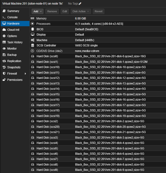
Your VM should look like this:
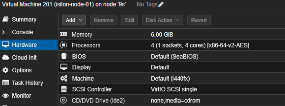
Assigning static MAC addresses and separating traffic using VLAN tags directly on the bridge (vmbr0) is the best way to maintain order and avoid identification headaches within OneFS.
Phase 2: OVA and Disk Import
Since you already have the hardware structure ready in VM 201, the correct flow is to import the OVA and then ensure the data disks are attached.
1. Import the OVA
If you haven’t already, extract the OVA and import the system disk (.ovf/.vmdk). This will create the node’s main (OS) disk.
Navigate to the path where the OVA is located:
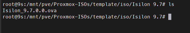
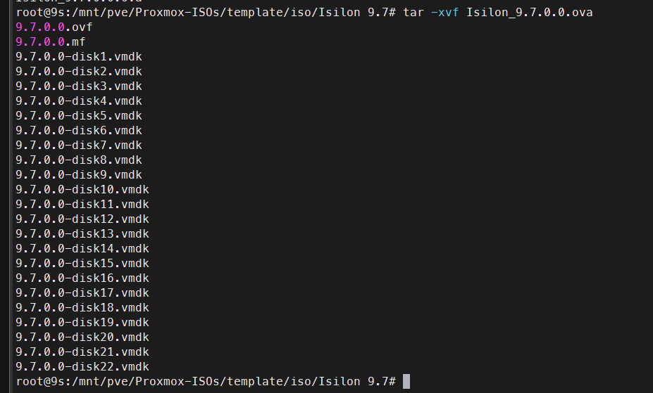
# Extract OVA contents
tar -xvf Isilon_9.7.0.0.ova
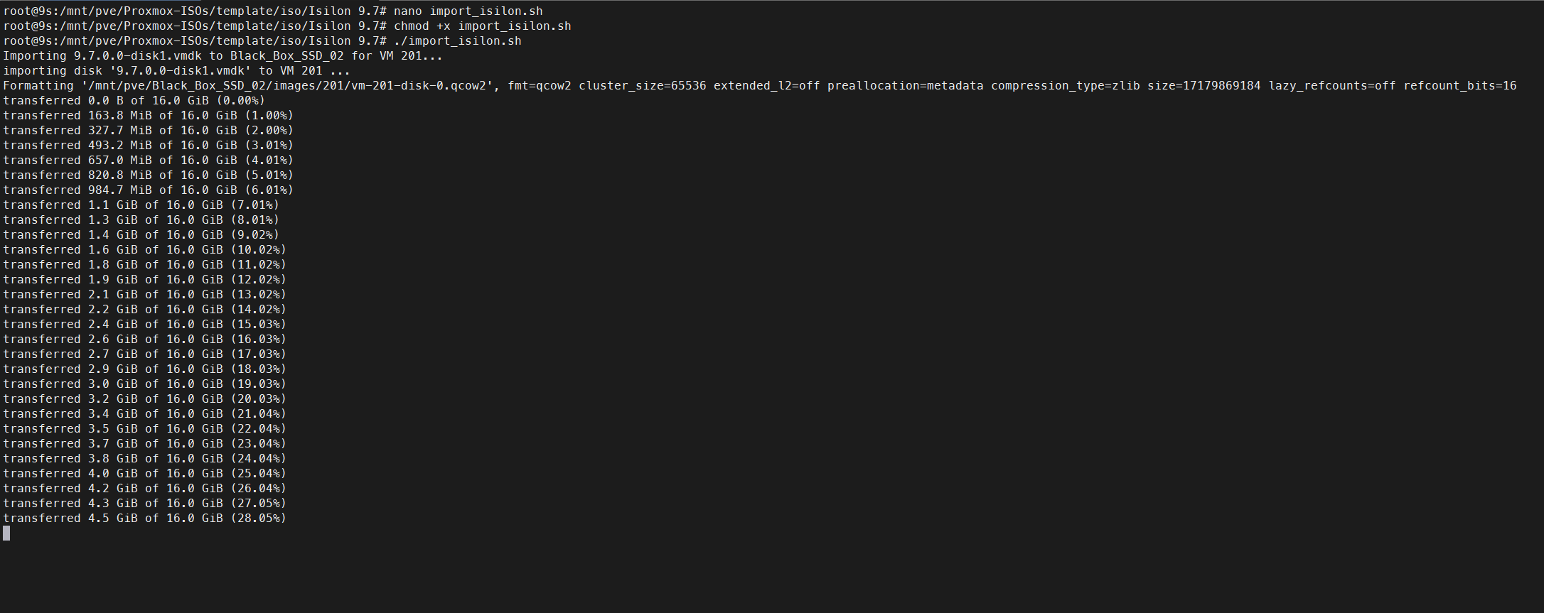
Create a file named import_isilon.sh, give it execution permissions (chmod +x import_isilon.sh), and run it in the same folder where you extracted the OVA. Adapt the VMID and Storage depending on where you want to store the disks.
#!/bin/bash
# Configuration variables
VMID=201
STORAGE="Black_Box_SSD_02"
# Loop through the 22 disks from the Isilon OVA
for i in {1..22}; do
FILE="9.7.0.0-disk${i}.vmdk"
# Check if the VMDK file exists
if [ ! -f "$FILE" ]; then
echo "Warning: $FILE not found, skipping..."
continue
fi
echo "Importing $FILE to $STORAGE for VM $VMID..."
# Convert and import the disk to the specified storage
qm importdisk $VMID "$FILE" $STORAGE --format qcow2
# Find the newly created unused disk name
UNUSED_DISK=$(qm config $VMID | grep "^unused" | head -n 1 | awk '{print $2}')
if [ -z "$UNUSED_DISK" ]; then
echo "Error: Could not find unused disk for $FILE"
exit 1
fi
# SCSI index (Disk 1 -> scsi0, Disk 2 -> scsi1, etc.)
SCSI_IDX=$((i - 1))
echo "Attaching $UNUSED_DISK as scsi${SCSI_IDX}..."
# Attach disk to SCSI bus
qm set $VMID --scsi${SCSI_IDX} "$UNUSED_DISK"
done
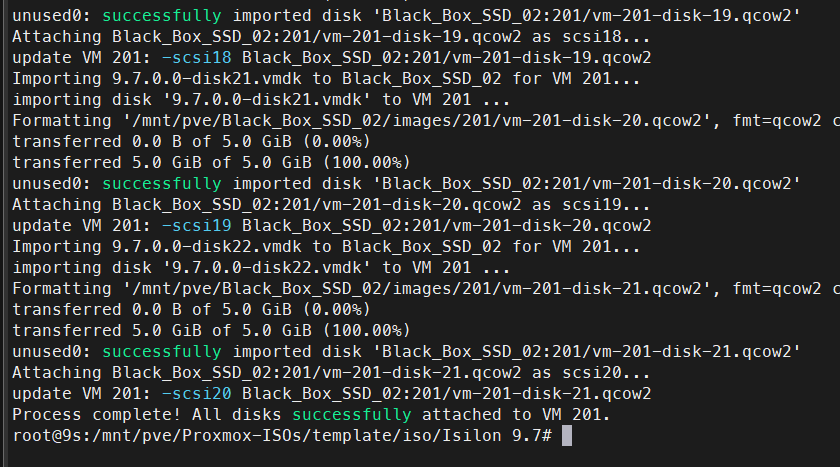
echo "Process complete! All 22 disks successfully attached as SCSI to VM $VMID."
2. Verify Disks in Proxmox
Once the script finishes importing, you can check the status of the disks in your Proxmox.
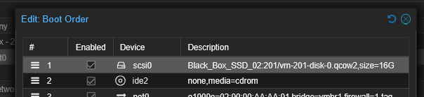
Before turning on or cloning Node 1, make sure the first disk (usually scsi0) is in position 1 in the boot order.
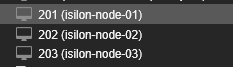
3. Clone for Multi-Node Cluster
Before powering on VM 201, perform a Full Clone twice to create Node 2 and Node 3.
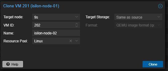
Once you have the 3 VMs, continue with the first VM.
Phase 3: Node 1 Initialization (Cluster Creation)
Take a snapshot before configuration. It is not mandatory but highly recommended in case something goes wrong.
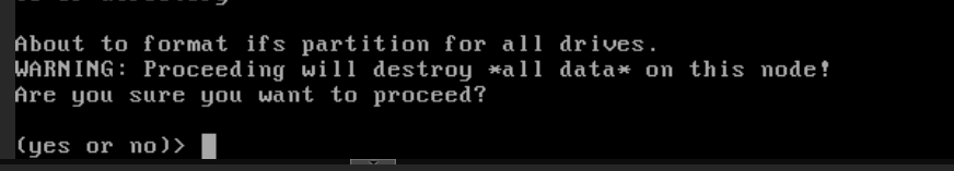
Power on Node 1, open the VNC console, and wait for the configuration wizard to load. At startup, it will ask to format all disks (ifs partition); press yes.
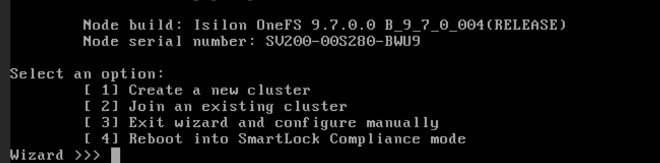
1. Cluster Selection
Select Create a new cluster (option 1).
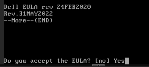
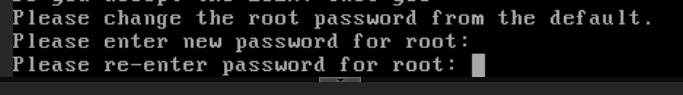
2. EULA and Credentials
Accept the EULA and define passwords for root and admin.

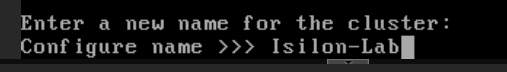
3. Cluster Naming
Name your cluster (e.g., Isilon-Lab).
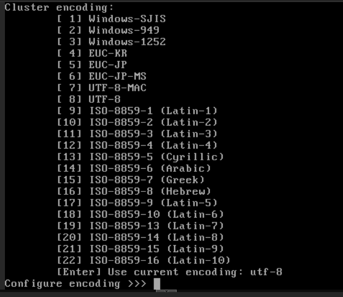
4. Encoding
Select the cluster encoding; use the default.
5. Int-a Configuration (Backend)
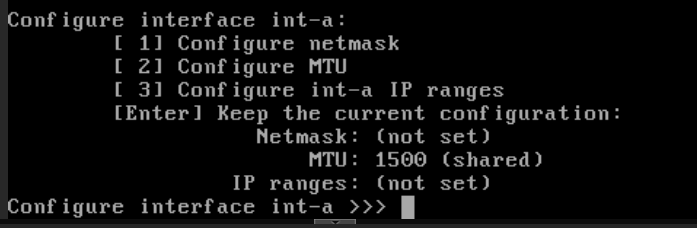
- Interface: Look for the one that matches MAC
02:00:00:AA:CC:01(likely listed asvtnet2). - Netmask:
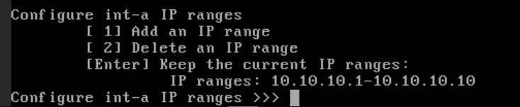
255.255.255.0 - IP Range: Use a fictional range, e.g.,
10.10.10.1to10.10.10.10. This traffic will live only within the isolated VLAN 1000.
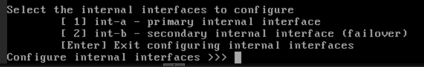
6. Int-b / Failover Configuration
Skip it (leave blank/Enter).
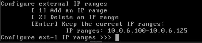
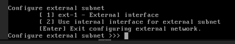
7. Ext-1 Configuration (MGMT)
- Interface: Matching MAC
02:00:00:AA:AA:01(likelyvtnet0). - Subnet:
255.255.255.0 - IP Range: Assign a range from your
10.0.6.100/24network (e.g.,10.0.6.21to10.0.6.125).
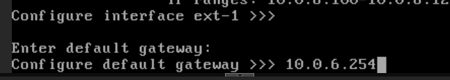
- Gateway: The IP of your default gateway for the
10.0.6.0network.
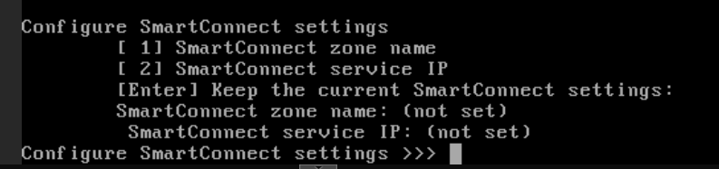
Skip the SmartConnect configuration for now; we will enable this service later exclusively for your SMB data network (10.0.5.0/24).
Phase 4: DNS and Timezone Configuration
Upon pressing Enter, the wizard will ask for final infrastructure parameters:
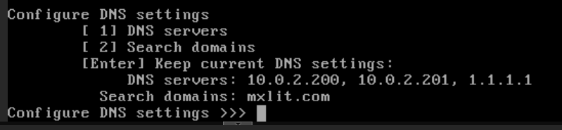
- DNS Servers: Enter the IP of your local DNS server (if you have Active Directory/Pi-hole in your lab) or a public one like
1.1.1.1. - Search Domains: You can leave this blank or use your lab domain (e.g.,
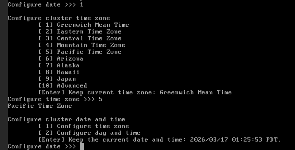
lab.local). - Timezone: Select your region (e.g.,
America/Tijuana) so cluster logs match your local time.
Join Mode Selection
Define the security behavior required when Node 2 and 3 join:
- Manual (Recommended): Any new node that starts and detects this cluster via the backend network can join if you select the option in its wizard. Fixed for lab environments.
- Secure: Requires an additional layer of authentication.
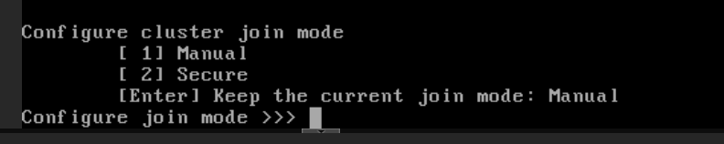
Press Enter to keep the default option (Manual). Type yes and press Enter to commit the changes. The node will begin formatting the 21 SCSI disks and building the /ifs file system.
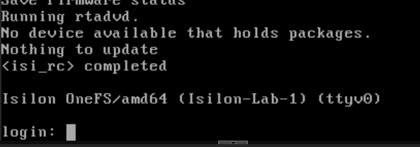
To log in, go to: https://10.0.6.100:8080/OneFS/Login
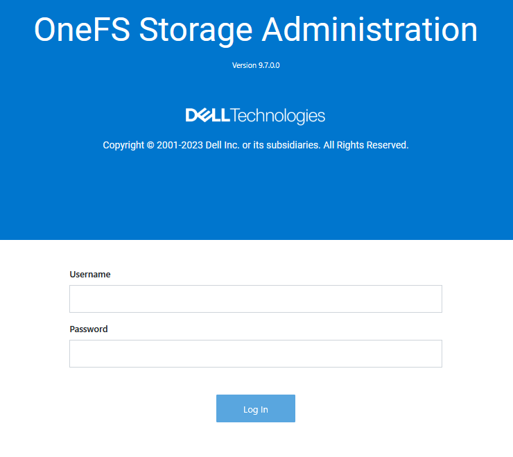
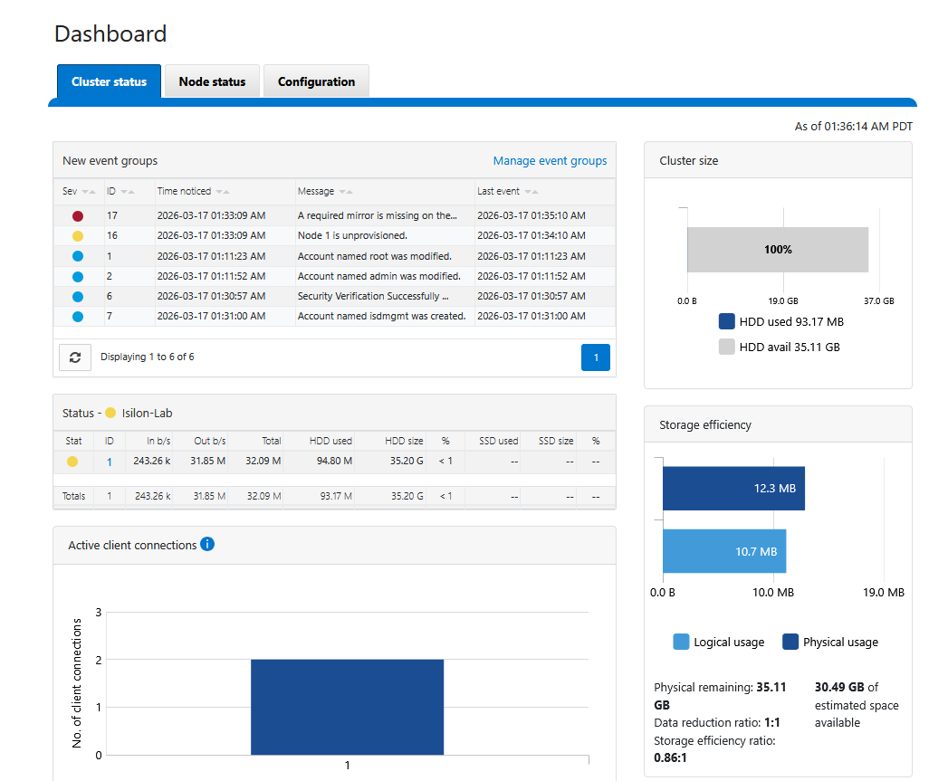
You should be able to see the web interface now.
If you cannot see the interface or ping it, check your VLAN tags; the management IP might have ended up on a different network.
Conclusion
With this, the first node of our virtual Isilon cluster is live and accessible via the web interface. In the next installment of this series, we will configure the joining of the remaining nodes and prepare the data network for SMB services.
End of transmission.